My electrical diagram

Anything electric, AC or DC

My electrical diagram

Postby TCJ » Sat Feb 05, 2022 9:54 pm

Would love to get some feedback on my electrical plan. Small teardrop with 99% DC loads. I'm including a small (and I mean small: 120W!) inverter to feed some outlets for plugging in phone/computer/camera chargers. I'll also have some 120V outlets for when we're plugged in to shore power, but I expect this will be very rare. Already have some of these parts; looking for confirmation of the general schematic before I buy the rest.

Some highlights, if the schematic isn't clear:
I wanted circuit breaker protection for both the 120V at input and separately for the charger and outlets, so I'm thinking about using a marine mains power panel.
Propex heater and inverter will have simple on/off switches on the positive side to keep them from drawing current when they're not needed.
Shunt will be used for a battery monitor; not sure which one yet.

Wiring_Schematic.jpg
Wiring_Schematic.jpg (82.81 KiB) Viewed 396 times
TCJ
Teardrop Builder
 
Posts: 45
Images: 1
Joined: Sun Jan 16, 2022 9:05 am

Re: My electrical diagram

Postby tony.latham » Sat Feb 05, 2022 11:11 pm

inverter to feed some outlets for plugging in phone/computer/camera chargers.


All three of those devices are DC devices. The in-line black boxes in 120-volt cords for these devices are inverters. So your plan is to go from DC to an AC Inverter and plug cords into it that invert back to DC.

Each time you invert, you lose about 20% of the power.

You can easily wire USB outlets directly to your 12-volt battery system. That'll take care of your phones and probably your camera. You might have to shop for a 12-volt cord for the camera that will plug into either a 12-volt outlet or perhaps a USB outlet.

My Mac charges on a USB-C outlet. So I have a USB-C plug I stick in a 12-volt outlet when I need to charge it. You can probably find a 12-volt cord for your computer.

Now.. If you think you want to wire in an inverter and an outlet, wire it in. I carry a small inverter in my tongue box that plugs into a 12-V outlet. I don't recall the last time I used it.

Just some thoughts. :thinking:

You may want an inline switch between your controller and panel. I can damage my Renogy if I disconnect the battery without unhooking the panel first.


Tony
User avatar
tony.latham
Gold Donating Member
 
Posts: 6900
Images: 17
Joined: Mon Jul 08, 2013 4:03 pm
Location: Middle of Idaho on the edge of nowhere

Re: My electrical diagram

Postby TCJ » Sun Feb 06, 2022 2:34 am

Thanks for the reply.

I understand about the inverters. Unfortunately, my experience with USB outlets is: (a) they fail all the time; (b) they often don't provide the right amperage for charging; or (c) they often don't charge very fast. It's just been so much easier to plug the dedicated adapter into a 120V circuit. I'll have USB outlets anyway (I should have labeled them); if they work, great, but if they don't, I want to have a backup alternative. The inverter I've been eyeing is efficient and small, and truth is, I probably won't be using it very often anyway. I just want to have the option.

Good catch about the switch between the charge controller and panel; I'll add that.
TCJ
Teardrop Builder
 
Posts: 45
Images: 1
Joined: Sun Jan 16, 2022 9:05 am
Top

Re: My electrical diagram

Postby tony.latham » Sun Feb 06, 2022 10:50 am

Unfortunately, my experience with USB outlets is: (a) they fail all the time...


There are a whole lot of cheap, unbranded USB outlets that are junk. This is the one that I use. It's a quality device that doesn't have an LED light:

https://www.amazon.com/gp/product/B07CJW3ZRP/ref=ppx_yo_dt_b_search_asin_title?ie=UTF8&psc=1

The first one I installed in a teardrop was in 2013. It works fine.

Tony
User avatar
tony.latham
Gold Donating Member
 
Posts: 6900
Images: 17
Joined: Mon Jul 08, 2013 4:03 pm
Location: Middle of Idaho on the edge of nowhere
Top

Re: My electrical diagram

Postby mtbikernate » Sun Feb 06, 2022 12:57 pm

I have a small inverter that's got enough juice to charge a laptop. I haven't used it with my teardrop, honestly. but I have it. no point in permanently wiring it in.

USB ports work well.

You have to pay attention to the A rating on them if you need a certain amount, though. I've had phones that were picky about such things, so I tracked down some USB ports that are rated to 3.0A, and they work great. Those are hard to find that aren't lit, though. When I bought them, I couldn't find any at all. But it looks like they're findable now. I may change out my lit ones to cut down on parasitic power draw.
mtbikernate
Teardrop Master
 
Posts: 122
Joined: Wed Apr 08, 2015 4:59 pm
Top

Re: My electrical diagram

Postby Tom&Shelly » Sun Feb 06, 2022 3:57 pm

mtbikernate wrote:I have a small inverter that's got enough juice to charge a laptop. I haven't used it with my teardrop, honestly. but I have it. no point in permanently wiring it in.

USB ports work well.

You have to pay attention to the A rating on them if you need a certain amount, though. I've had phones that were picky about such things, so I tracked down some USB ports that are rated to 3.0A, and they work great. Those are hard to find that aren't lit, though. When I bought them, I couldn't find any at all. But it looks like they're findable now. I may change out my lit ones to cut down on parasitic power draw.


We used these USB ports

152991 153425

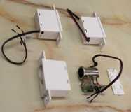
(Not the cigarette lighter outlets--they are rated for too low of a current draw.) I took them apart and clipped the LED so they wouldn't glow in our dark cabin. That cuts the parasitic current draw by about half. I think the rest is wasted on the internal DC-DC converter taking the 12 volt input to 5 volts.

These charge our phones slowly, but I bought them 4 or 5 years ago. We later bought the "identical" product, except it was colored black, from the same company (via Amazon) and found one of the four USB outlets had a lightning icon next to it, and, sure enough, it fast charges our phones. No change in the description on Amazon, so I don't know how one could tell for sure what one is getting.

We also bought some round USB outlets (look like the ones Tony pictured), but I discovered they generate a lot of radio noise. Of course, if you aren't going to use radios near your teardrop, that may not be an issue.

Tom
172912 170466 173366
Tom&Shelly
Palladium Donating Member
 
Posts: 2203
Images: 1961
Joined: Tue Sep 05, 2017 3:27 pm
Location: Upstate New York/New Mexico
Top

Re: My electrical diagram

Postby mtbikernate » Sun Feb 06, 2022 6:13 pm

Being that my camper is one that I bought, not built, it was already set up with the round socket type mounting plate for the 12v outlets. so replacing with round socket type fixtures is the way to go for it unless I want to make extra work for myself.

there are rocker switch type panels you can use, as well, if you're building from scratch. Those are pretty common, too.

I just bought a couple unlit dual 3.0A USB ports.

there's already a voltmeter in one of the 3 sockets that's always bothered me when I'm trying to sleep. I bought a replacement voltmeter that has a switch that allows you to turn the display off. reduce the parasitic draw AND the ambient light at night.

I also have another 3-port panel that I will be installing at the rear cabinet. I put some 12v ports in the galley awhile back, as well. I put a toggle switch on those so I can shut them off entirely and completely eliminate parasitic draw from them.

These things are just dead easy to replace if they end up going bad. They use simple blade connectors on the back and a thumb nut to snug them down to the mount.
mtbikernate
Teardrop Master
 
Posts: 122
Joined: Wed Apr 08, 2015 4:59 pm
Top


Return to Electrical Secrets

Who is online

Users browsing this forum: No registered users and 40 guests