The Poet Creek Express - Foamie Hybrid

Canvas covered foamies (Thrifty Alternatives...)

Moderator: eaglesdare

Re: The Poet Creek Express - Foamie Hybrid

Postby KCStudly » Tue Apr 29, 2014 10:49 pm

Thanks Ned. I was aware of that, and I even wonder if the fact that the recommended jig settings don't complete the pilot hole are intended to help keep the screw from shoving the alignment off. My deal on this joint is that I won't have any way to clamp it tight first, so I want to make sure that the first couple of screws don't bite both sides with a gap in the middle. By cleaning out the hole on the attached part I can be sure that the screw will pull the piece up tight. May not be an issue, but I don't want to find out in the middle of a big glue up.
KC
My Build: The Poet Creek Express Hybrid Foamie

Poet Creek Or Bust
Engineering the TLAR way - "That Looks About Right"
TnTTT ORIGINAL 200A LANTERN CLUB = "The 200A Gang"
Green Lantern Corpsmen
User avatar
KCStudly
Donating Member
 
Posts: 9616
Images: 8169
Joined: Mon Feb 06, 2012 10:18 pm
Location: Southeastern CT, USA

Re: The Poet Creek Express - Foamie Hybrid

Postby Wolffarmer » Tue Apr 29, 2014 11:07 pm

Parts for my Suzuki transmission came in and I did not work today so I got that changed. Actual fixing took just under an hour. Driving around to warm up the oil so it would drain better. And jacking it up on my rack. And jacking it up a bit off center and having the Suzuki fall off to one side at an angle from about 20 inches above the floorand getting things righted took another hour. Oops
:oops:
When it was at that angle found there is a fuel leak someplace around the filler tubes/pipes. I must have caused that when I replaced the fuel pump a few years ago. Will look into that later. But the Suzuki is parked on my basketball court and no leaks yet. Yippy. You need to see my lifting device to know how I got it into that precarious position. Try not to do that again. LOL

Randy
"these guys must be afraid of the dark"
User avatar
Wolffarmer
Donating Member
 
Posts: 4612
Images: 309
Joined: Wed May 02, 2007 1:32 pm
Location: Idaho Rupert

Re: The Poet Creek Express - Foamie Hybrid

Postby KCStudly » Tue Apr 29, 2014 11:15 pm

Yowser!!! Almost flipped it and burned it to the ground all indoors and going zero mph. Some trick. What will you do for an encore? :lol: :lol: :lol:

Truth, glad you are safe. :thumbsup:
KC
My Build: The Poet Creek Express Hybrid Foamie

Poet Creek Or Bust
Engineering the TLAR way - "That Looks About Right"
TnTTT ORIGINAL 200A LANTERN CLUB = "The 200A Gang"
Green Lantern Corpsmen
User avatar
KCStudly
Donating Member
 
Posts: 9616
Images: 8169
Joined: Mon Feb 06, 2012 10:18 pm
Location: Southeastern CT, USA
Top

Re: The Poet Creek Express - Foamie Hybrid

Postby KCStudly » Fri May 02, 2014 12:05 am

So I hadn’t thought far enough ahead on the joinery for the locker door frame. I was thinking I would biscuit join the pieces so cut the stiles and mullions to the size of the openings. Didn’t take long for me to realize that when I cut the grooves for the panels to slide into, it would wipe out where the biscuits would need to go and would leave unsightly openings on the side edges. Making blind grooves was a complex option and I don’t have a 3/16 inch cutter for the router (… well, maybe Karl has a metal cutter for the mill). I thought about making splines and cutting grooves in the ends of the stiles and mullions, too, but I wasn’t confident (yet) that I could achieve the required fit (in hindsight this would have been the best solution). What I ended up doing Wednesday was getting another shorter piece of 1x3, cutting longer stiles and mullions (had to rip the stiles to 1x2, as well as cross cut), and used the table saw to create tenons to fit the grooves.

First to groove the boards. I wanted to be sure to hold the boards absolutely flat to the rip fence so I made a second feather board.
Image

Here’s the grooving setup. You wouldn’t normally put a feather board after the blade because it would pinch the cut wood into the blade and create a kick back/ejection hazard. However, in this case I was not cutting thru the board, and since the groove would be relatively narrow and shallow, there was no concern about it pinching. The little piece was for setup. The panels will be 3/16 thk (5 mm), the blade is 1/8 inch kerf, and the frame material is 3/4 thk, so I set the blade 9/32 from the fence (3/4 – 3/16 divided by 2). By running each board thru once, then flipping and running it again I could be sure that the groove was in the middle of the edge of the board (as learned from watching Norm).
Image

Because most of the boards were 3x, same as the rip fence, the wide push paddle was very stable riding on top. For the narrower stiles I used two of the slender push sticks; one to push and hold to the fence, and the other to hold the front of the board down.
Image

Here are all of the grooves.
Image

Here there aren’t any tenons yet. I just butted the boards together and slipped a scrap of ply in the grooves to get an idea of how it would look.
Image

Next up was making the tenons. I had some success.
Image

But not without some “learning experiences”. Here we are looking down on the tenoning set up after I made a correction. Prior to this I had the stop block further back from the blade and there was occasion to slip one of the stiles past the stop and make a false cut :x . Also, after zipping the miter back and forth many times nibbling away at the tenons, I started to notice that the boards weren’t running perpendicular to the stop any more.
Image

What I found was that each time I slide the miter back into position I was bumping the clamp with the end of the miter backing board. Since I had not checked to see that the tab for the miter index was in the proper position, this tap, tap, tapping caused the miter to turn off of 90 deg. Fortunately, that had the effect of pushing the boards farther away, so once corrected it was a simple matter to make one more pass on each side to make sure the shoulders where all square.

Here is a pic of the miter with the catch swung away from the index stop.
Image

And with it in place.
Image

The next thing I learned was that there really is a need for the locks on the saw adjustment handles. When we went thru the saw we weren’t able to free these up. When I set the blade height for the tenons (after numerous trial and error attempts on scrap) I got it just right, but by the time I got to the last tenon they were running much thicker. Okay, a whisker or three thicker, but for a glue joint that’s enough to make a difference between fitting and not fitting.

So rather than mess with the saw and risk going too far the other way, or bother getting the router table out, I just used the small scraper and sanding block and hand tuned each of the joints. Got thru half of them but at 9:15pm it was time to go home.

Tonight (Thursday) I cut a replacement stile, ran the tenons from last night’s set up, and then switched back to the grooving setup to run those.

Then I finished the hand fitting and did another dry fit assembly.
Image
Image

The cutout from the front wall should have been big enough to cut the three panels from (…if I had taken a little more care… :oops: ), but because I had cut it with the skil saw it was slightly irregular on all sides. In order to get a good true side I screwed it to a scrap with a good edge and used that against the rip fence to get a true edge to start. Here is the ply with the straight edge attached.
Image

After a series of cross and rip cuts I had 3 panels. Somehow the first longer middle panel came up short. Not sure if I ran 3 at the shorter length by mistake and ended up running out of stock, or if I just goofed. Had to dig another small piece of Okoume out of my drop pile and make some more cuts to get the one you see here; all three panels just sitting on top.
Image

It was getting late again, but I couldn’t resist slipping the panels into the frame to see how it is gong to look.
Image
Image

I had one of those “Je ne sais pas” moments today going from getting my teeth cleaned at the dentist’s to Mecca. How many times have I done this during the build? Man I have been working on this project for a long time! The seasons are ticking by.
Last edited by KCStudly on Sun May 25, 2014 11:30 pm, edited 1 time in total.
KC
My Build: The Poet Creek Express Hybrid Foamie

Poet Creek Or Bust
Engineering the TLAR way - "That Looks About Right"
TnTTT ORIGINAL 200A LANTERN CLUB = "The 200A Gang"
Green Lantern Corpsmen
User avatar
KCStudly
Donating Member
 
Posts: 9616
Images: 8169
Joined: Mon Feb 06, 2012 10:18 pm
Location: Southeastern CT, USA
Top

Re: The Poet Creek Express - Foamie Hybrid

Postby Hardryder56 » Fri May 02, 2014 1:40 pm

Great looking work there. Not fully sure how your original plan was but blind dados can be made by marking on the fence the leading and trailing edged of the saw blade then marking on the wood where you wanted the dado to start and finish. Start the saw and slowly drop the wood onto the blade at your start mark and move it to the end mark, lift up the wood or turn off the saw and let the blade come to a stop. That way you cut the groove for the panel and the biscuits at the same time. Just a thought but your way worked out very well.
Tom
Coffee is like liquid hugs, it warms you from the inside out
Hardryder56
Teardrop Advisor
 
Posts: 92
Joined: Mon Nov 25, 2013 5:04 pm
Location: Lake Conroe, TEXAS
Top

Re: The Poet Creek Express - Foamie Hybrid

Postby KCStudly » Fri May 02, 2014 11:13 pm

Thanks for the tip Tom (Hardryder56). I was thinking about using the router that way because the plunges could be relatively straight in. I’m not sure that I could start and stop the groove at full depth with the table saw the way I would need to given the curve of the blade. Plus I would be a little nervous about trying it, but it is something to keep in mind.

Onward. Doing the locker door the way I want to, with natural stain on the maple frame and red chestnut on the panels means that I will have to think about the assembly and finishing steps very carefully. I want to round over both the outer edges and the edges surrounding the panels. However, the guide bearing and its retainer bolt on the round over bit would need to poke thru the panel to work properly, so the panels have to be out to run the router around. On the other hand, if I were to try routing the edges before assembly the corners probably wouldn’t match well, or I could make a mistake a lot easier (catch a corner, roll past a corner, etc.).

So I think I have come up with a reasonable compromise. The plan is to glue most of the door frame leaving one rail loose so that I can still get the panels in; clamp the partial frame assembly and loose rail together with it shimmed up in the pipe clamps to the point where I can run the router around the inside edges; stain the panels and install them; glue the loose rail on; route the outside edges; then mask the panels and stain the maple; and finally, polyurethane the whole assembly as one. That’s the plan.

To avoid any sharp edges and continue the round over theme, I wanted to put a 1/4 inch radius on the four corners. That way when I route the radii on the perimeter of the faces of the frame the bearing (and radii) will roll around the corners leaving nice soft edges. To do the corner edges I would need to hold the long rails up on edge on the router table and push them past the cutter using a miter gauge. Ideally the miter gauge would be backed up by some wood to help prevent tear out.

The miter that came with my router table is pretty lousy. The head is cast plastic and the front face is not perpendicular to the table due to draft designed into the molding process of the plastic. The underside is hollow with a couple of cheesy slots that are meant to attach a face board, but it just seemed hokey to me. I took a look at the miter gauge that came with the small crap saw and found that it was a little nicer, and it fit the slot in the router table. This one is die cast aluminum; the face is perpendicular to the table; it has a Teflon insert on the bottom to make it glide easier; and the feature for attaching a face board is more robust, and accessible from the top. All I had to do was attach a face board.
Image

I suppose that they intended for me to use flat head bolts thru the face of the board with nuts and washers on the back, but the bearing areas for the washers are recessed making it hard to get a wrench on; and the closest thing we had on hand for suitable fasteners were lag bolts… and they were about 1/4 inch too long. So I made these aluminum spacers on the lathe. They killed two problems, they made the lag bolts the correct length and prevented them from sticking thru the board; and they spaced the head of the lag out to where I could fit a wrench.
Image

With that setup I was able to round over the outside corners of both the top and bottom rails.
Image

Masked around the glue joints along one rail and glued the one side up using the loose rail for alignment and checking for square.
Image

Then I stained the panels front and back, and along the edges, too.
Image

Tomorrow Karl and I are getting up early and going to the annual tractor swap meet/flea market. Maybe I’ll score some more Coleman stuff!
KC
My Build: The Poet Creek Express Hybrid Foamie

Poet Creek Or Bust
Engineering the TLAR way - "That Looks About Right"
TnTTT ORIGINAL 200A LANTERN CLUB = "The 200A Gang"
Green Lantern Corpsmen
User avatar
KCStudly
Donating Member
 
Posts: 9616
Images: 8169
Joined: Mon Feb 06, 2012 10:18 pm
Location: Southeastern CT, USA
Top

Re: The Poet Creek Express - Foamie Hybrid

Postby Wolffarmer » Sat May 03, 2014 12:25 am

Hey, I could use the base for the fuel setting bulb for a 1940 International M. It screws into the bottom of the fuel tank, sediment bulb goes on that and the fuel line screws into it.

Just kidding. but on mine where the fuel line screws in is stripped. kind of dangerous to run that way. Even for me.


Oh, good work. Soon will be going mobile
"these guys must be afraid of the dark"
User avatar
Wolffarmer
Donating Member
 
Posts: 4612
Images: 309
Joined: Wed May 02, 2007 1:32 pm
Location: Idaho Rupert
Top

Re: The Poet Creek Express - Foamie Hybrid

Postby KCStudly » Mon May 05, 2014 3:42 pm

Randy, I wish I had known about the tractor swap sooner. I would have gladly looked for your needed fuel separator. I bet I could have found one, too. That is exactly the type of thing that shows up there by the bin full! Post a good picture of what you need and I will look again next year.

I’ve been working along and loading pictures up (lots of them), but have fallen behind on updates. Let’s get caught up, shall we?

After scoring some tools and white gas appliances at the swap meet (detailed thread here) I spent the rest of Saturday working on the locker door assembly.

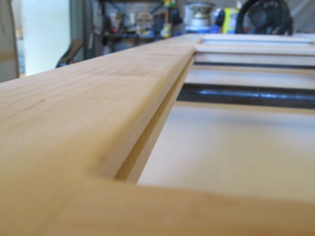
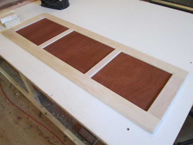
Here is the door after gluing one rail, removing clamps, removing tape and scraping the glue joints.
Image

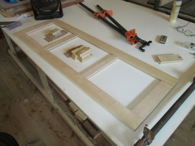
Oh happy, happy joint.
Image

By fitting the loose rail, shimming the assembly up off of the pipe clamps, and clamping it up with the toes of the clamps below the face of the frame I was able to run the router around the inside edges of the panel openings using the 1/8 inch round over bit; two operations, inside face and out.
Image

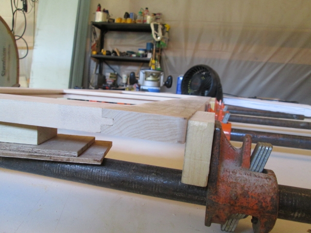
With a lot of handwork and a scrap of 220 grit wrapped around a small stick, I was able to dress up the corners where the router couldn’t reach.
Image
Image

The “front” outside edge of the face got 1/4 inch round over. Took a couple of different clamp ups to do the edge at the joint, then move the bar clamps out of the way to get the rest.
Image

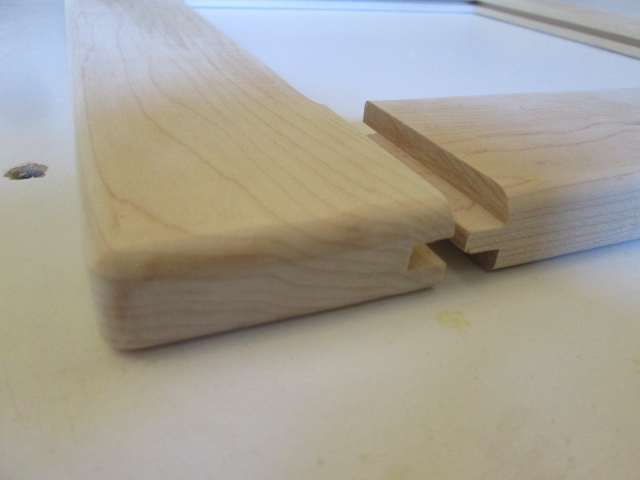
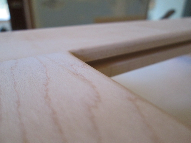
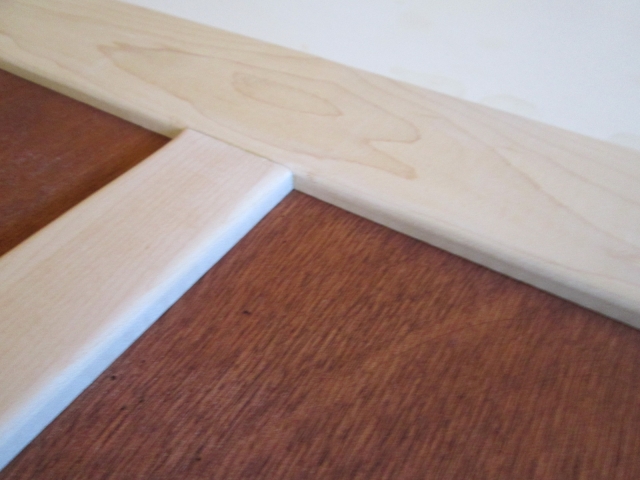
Here you can see how I blended the inside corners of the mullions while clamped, prior to installing the panels and having them be in the way (shown separated after unclamping).
Image

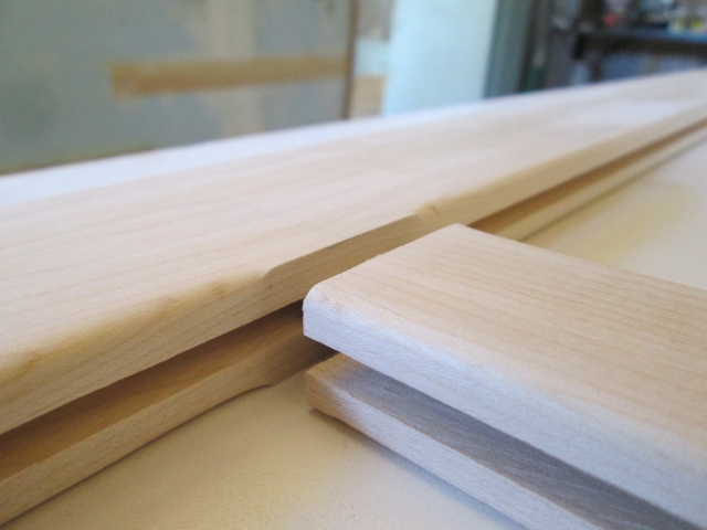
The outside edge on the “back” face of the frame where it closes against the wall got the 1/8 inch round over to ease the edge and prevent head knockers. Here you can see the profile inside and out, front and back.
Image

Another dry fit. I’m really happy with the way this is turning out!
Image
Image

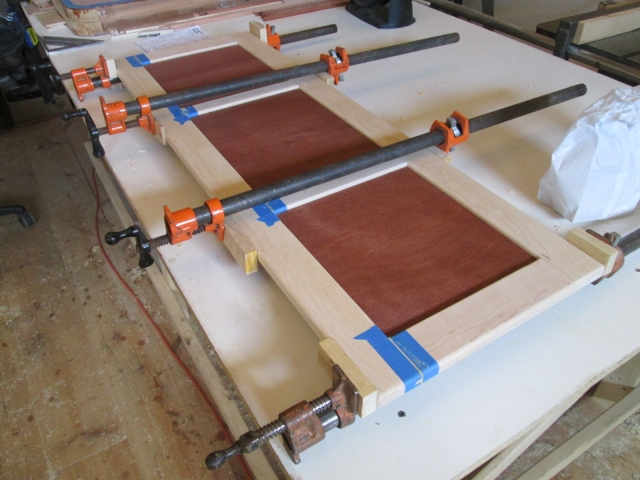
Finished up the day by masking and gluing up the second rail with the panels installed. So that was about 5 hrs at the swap and another 7 hrs fussing with details.
Image

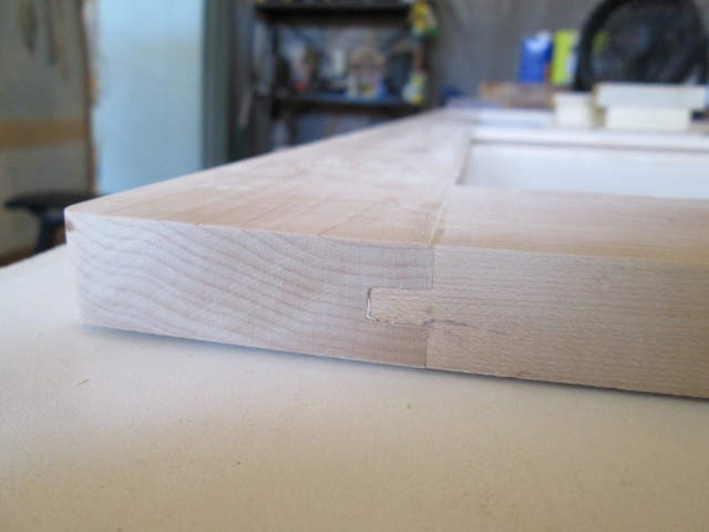
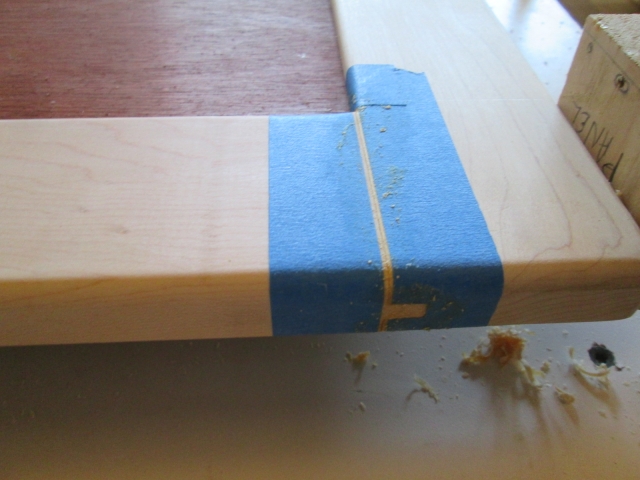
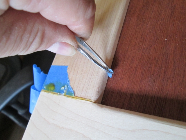
Sunday I put in another 6 hrs dressing the glue up and working on fitting the door hardware. Here is one of the glue joints “fresh out of the mold”.
Image

The tweezers I got at the swap meet have already been put to use!
Image

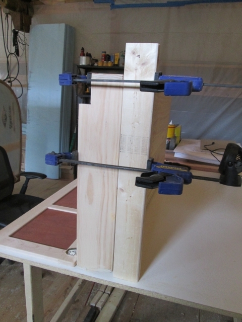
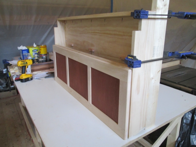
To fit the door to the locker hinges I had to prop the locker upside down on the bench. Because the slanted top wouldn’t let it stand on its own, I clamped a piece of 2x3 on the front to act as a foot.
Image
Image

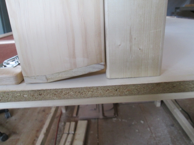
Because the hinges are articulated to swing the door out, then back down the instructions call for a 3.5mm gap so that the corner of the door does not hit. Rather than use the paper template supplied, I used a couple of shims that matched the template; one seen here.
Image

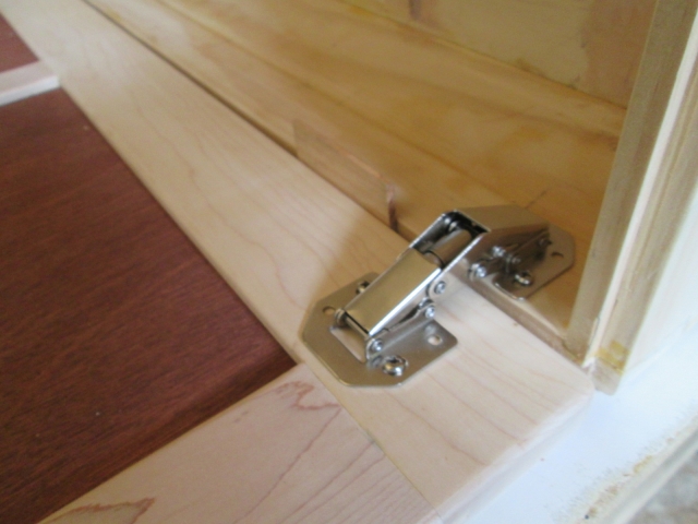
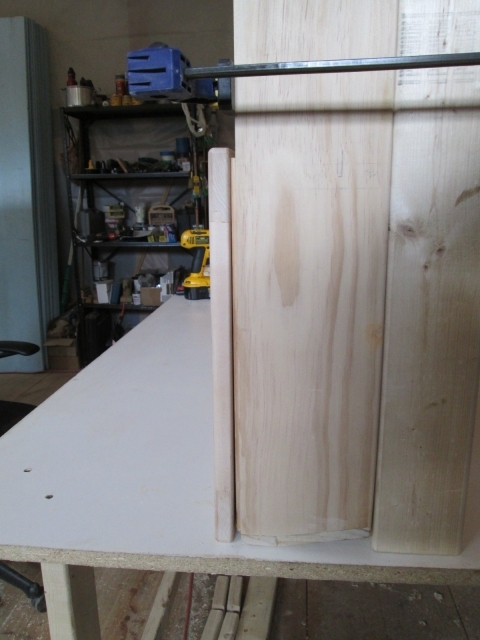
Still upside down, here it is with the door closed.
Image

You can see how the hinge holds the panel out a little at the top (bottom of pic), but no bother.
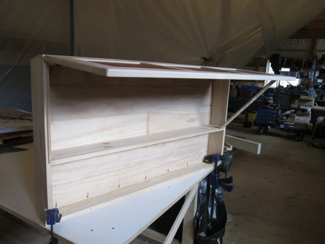
Image

Here it is upright.
Image

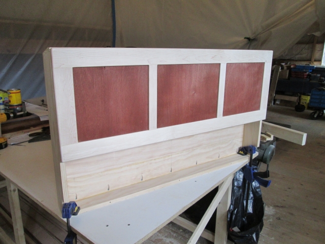
The springs in the hinges weren’t sufficient enough to hold the door up, so the stick is just there for the photo op.
Image
Even if I added a couple more hinges of this type, I don’t think it would be enough, and if I put more in the middle of the cabinet I think that would start to block access more than I want. I’m shopping for some folding props; something simple. Any suggestions?

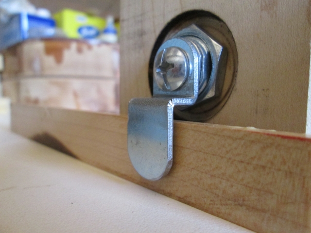
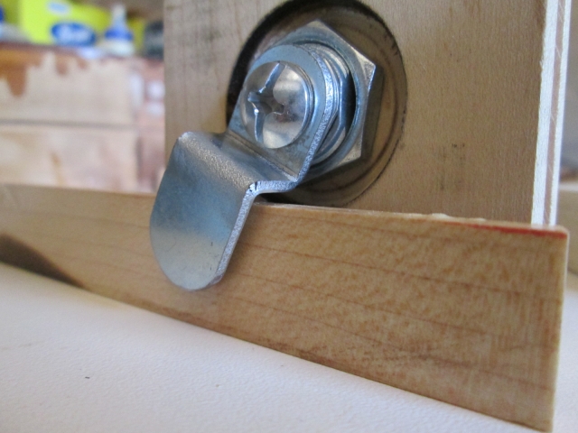
Next up I wanted to do a test run on mounting the cam style lock cylinder, and making a slot for the striker. The lock is sized for 9/16 maximum thickness, so I would need to recess the double-D anti rotation washer and gland nut in the back side of my 3/4 inch thick frame rail. Using the milling machine, I bored the required 3/4 inch diameter hole for the barrel of the lock using a Forstner bit, then on the same center (concentric) I used the 1-1/4 slugger to counter bore the washer recess.
Image

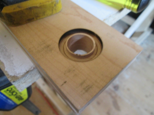
That left a small lip that needed to be chiseled out.
Image

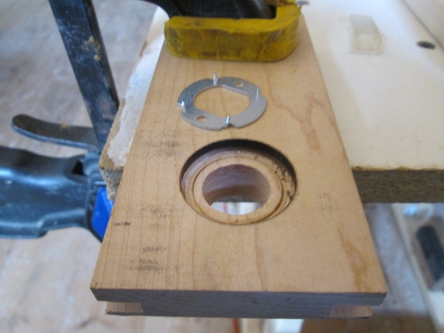
You can also see the double-D washer with little spiky cleats that will get pressed into the recess (I left it out for now). Image

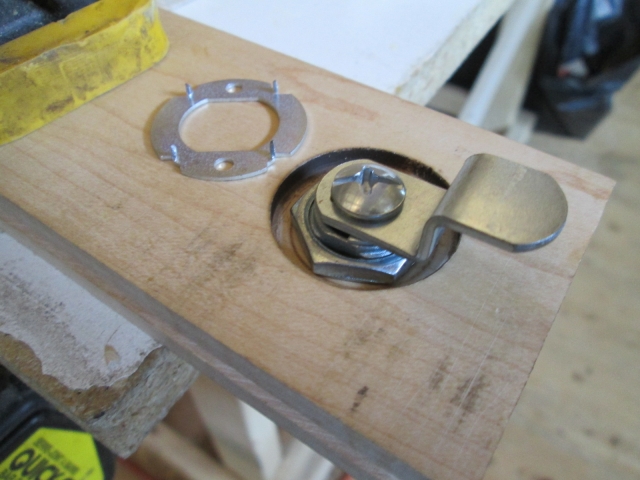
The “front” side of the lock mockup.
Image
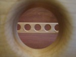
I wasn’t sure if I would be able to chisel out a decent slot for the cam, so I cut another scrap of pine to simulate the divider sill in the locker and gave it a go. Because of the depth of the 1/4 inch wide slot required, that I couldn’t get the tip of the utility knife down in the hole far enough to cut the ends of the grains, and the fact that I don’t have a 1/4 inch wide chisel, I made one out of a piece of bar stock.
Image

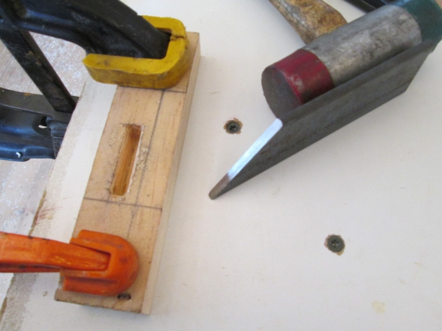
Harvested from Karl’s scrap bin, this piece of 1/8 thick SS strip will get milled into a slotted striker plate and will be recessed into the sill with a couple of flat head SS screws (shown long and off to the front side).
Image
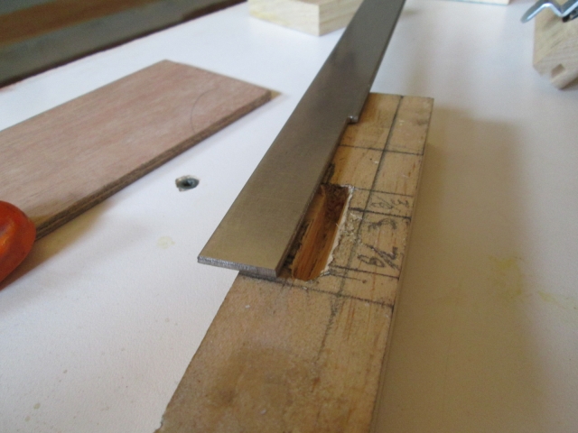
I had some issues with the slot (see more below). In hindsight, I will have a “do over”. I think I can fit the plunge router into the locker opening and use the 1/4 inch straight cutter to make a cleaner slot.

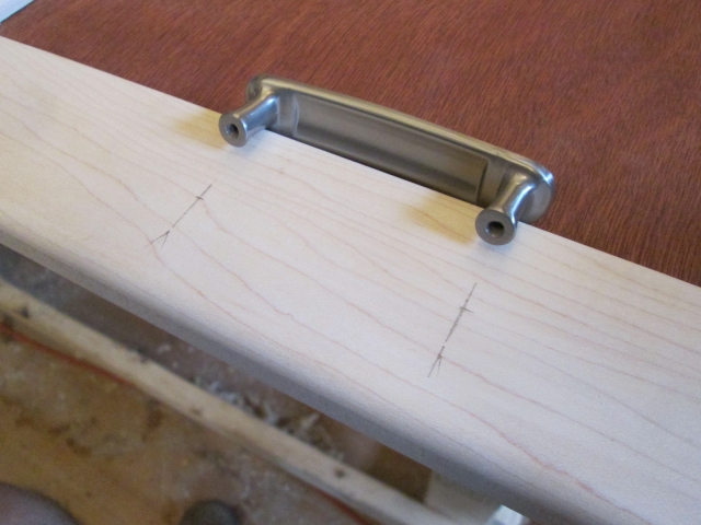
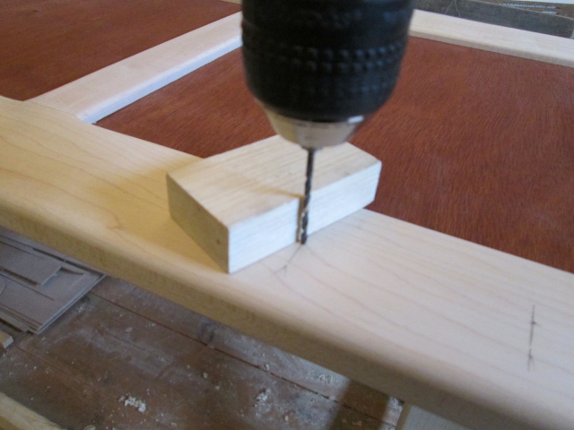
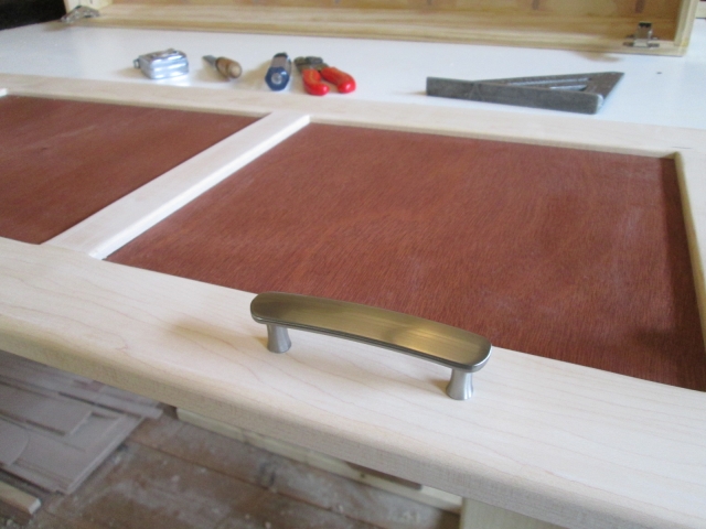
I was very careful laying out for the handle placement. I really wanted the handles to look centered on the outside panels, and on the height of the bottom rail, and I didn’t want them to look crooked. Careful measuring and marking with a quick square, then pricking the center mark with the tip of a deck screw helped get the pilot drill started exactly where I wanted it.
Image
Image

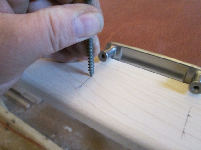
I used a small block as a guide, checking two axes to plumb the pilot drill bit before drilling up for the 8-32 screws.
Image

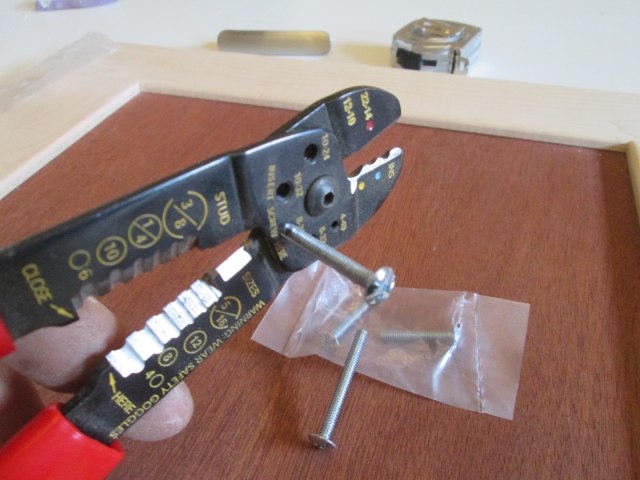
There were two different length screws that came with the pulls. The shorter ones only stuck out about 1/4 inch, but if I cut the longer ones down I could get 3/8 inch engagement. I can be a little heavy handed sometimes so I hedged my bet on stripping out the threads by cutting down the longer screws. Used the small thread shearing feature on my wire strippers.
Image

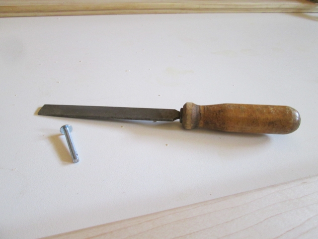
Just to be sure, and maybe to justify the purchase, I used the newly acquired fine file to remove the burrs and chamfer the lead threads to make sure that they didn’t wipe out the female threads in the pulls.
Image

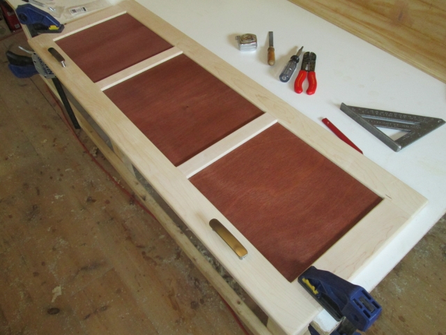
Prefitting the hand pulls worked out well.
Image
Image

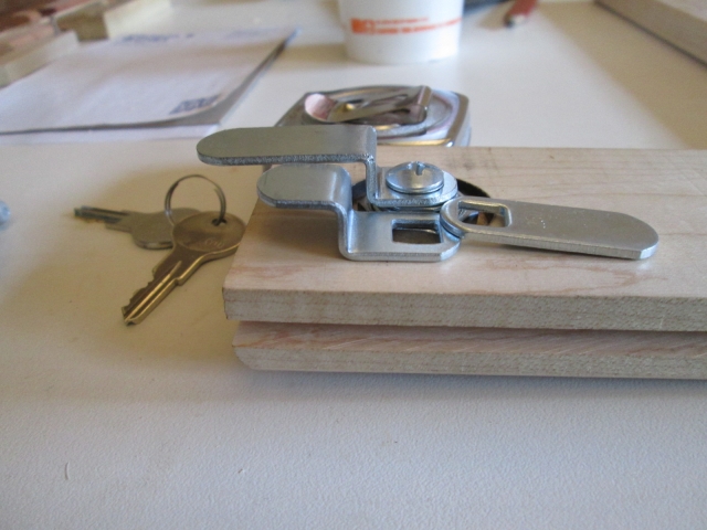
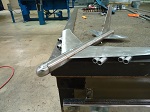
Getting back to the cam lock striker slot. With the tumbler centered where I wanted it the zig in the cam’s offset would clear at rest, but when swinging thru its arc the sides of the zig would hit the sill. Covered up by the striker stock shown in the picture up above, was another divot that I chiseled out trying to get it to swing. I didn’t like that, and at first I thought I would just raise the tumbler up about 1/4 inch, but that didn’t sit well with me either. So after mulling it over while I worked on these other things I struck upon a better solution. The lock set comes with three different cams: a short flat, a short offset (or “zig-zag”), and a long flat. By bending the long flat cam closer to the screw hole using a combination of Karl’s sheet metal brake (for the first bend) and a vice with a makeshift punch for the second bend, I was able to provide extra clearance for the cam to swing.

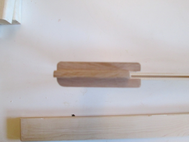
Here is the difference in offsets.
Image

Here it is after trimming to length and rounding over on the Bader (belt sander).
Image

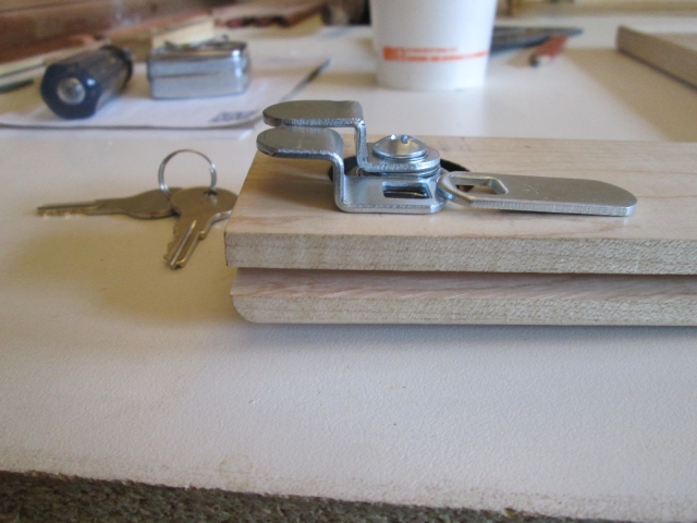
And here is a mockup sequence showing how the cam can now swing without hitting the sill. Note how there is less clearance part way thru the swing.
Image
Image

On the way home I stopped at The Orange and got some short #6x1/2 SS flat head screws for the striker plate, and some bright zinc plated ones to use screwing the front wall skin to the cabinet ledgers.

So now it is Monday. I’m still at work (though off the clock). I have a couple of wrought railing end caps to blast for Karl and am going to see if I can get the striker plate milled out.

All for now.
KC
My Build: The Poet Creek Express Hybrid Foamie

Poet Creek Or Bust
Engineering the TLAR way - "That Looks About Right"
TnTTT ORIGINAL 200A LANTERN CLUB = "The 200A Gang"
Green Lantern Corpsmen
User avatar
KCStudly
Donating Member
 
Posts: 9616
Images: 8169
Joined: Mon Feb 06, 2012 10:18 pm
Location: Southeastern CT, USA
Top

Re: The Poet Creek Express - Foamie Hybrid

Postby GPW » Mon May 05, 2014 5:05 pm

BEAUTY cabinetry KC .... :applause: 8) 8) 8)
There’s no place like Foam !
User avatar
GPW
Gold Donating Member
 
Posts: 14912
Images: 546
Joined: Thu Feb 09, 2006 7:58 pm
Location: New Orleans
Top

Re: The Poet Creek Express - Foamie Hybrid

Postby RandyG » Mon May 05, 2014 5:35 pm

Nice work as always Kc. Do you think you will need a prop on both sides of the door? I know you only have the one stick holding it in the pic but those props can be a little flimsy. Could become a pain with one on the side you are opposite of while trying to close it. Gas prop maybe. I know you said simple but it just got me thinking, not always a good thing. :?
Randy
Aircraft fabricator, novice carpenter, electrical apprentice, audio engineer dropout.
Build thread - http://www.tnttt.com/viewtopic.php?f=50&t=54126
User avatar
RandyG
500 Club
 
Posts: 695
Images: 115
Joined: Thu May 10, 2012 6:52 pm
Top

Re: The Poet Creek Express - Foamie Hybrid

Postby KCStudly » Mon May 05, 2014 8:27 pm

.
Thanks for the compliments!

RandyG, I did stop and look at the simple folding hinge style props available at Ho-De-Po, but they only had brass plated, no nickel or even chrome. I haven't ever used one, so I had assumed that it would be sufficient, but I can see where you are probably right; might be flimsy. I am hoping that I can get away with just one prop. The door is about 45-5/8 wide x 15-1/2 tall, so not out of reach, but if I have to manually actuate something to get the prop to fold, then I need one hand on the lid and only one free to unlatch.

The hinges I used are really intended to be for euro style frame-less kitchen cabinets. Although the info hinted that they might hold a lifting lid up, I think they are better suited to just holding a side swing door open or closed.

I had looked at these trick adjustable tension spring loaded units from Hafele. Anybody have any experience with them? I guess I need to weigh the door and see if it falls within the specs; there is also a smaller version available.

Here's what I made this evening, the lock strike plate for the locker door.
Image
Image
Last edited by KCStudly on Tue May 06, 2014 6:16 am, edited 1 time in total.
KC
My Build: The Poet Creek Express Hybrid Foamie

Poet Creek Or Bust
Engineering the TLAR way - "That Looks About Right"
TnTTT ORIGINAL 200A LANTERN CLUB = "The 200A Gang"
Green Lantern Corpsmen
User avatar
KCStudly
Donating Member
 
Posts: 9616
Images: 8169
Joined: Mon Feb 06, 2012 10:18 pm
Location: Southeastern CT, USA
Top

Re: The Poet Creek Express - Foamie Hybrid

Postby atahoekid » Mon May 05, 2014 10:35 pm

KC, as always, very nice work. Someone above in this thread stated that watching you made him feel like a hack with power tools. I share the sentiment. The time and attention to detail are just astounding. It shows in the results... Congratulations! Can't wait to see this one finished. Too bad we live on opposite sides of the continent, I'd like to see this one in person!!!
Mel

"Believe in your abilities... Remember amateurs built the ark, professionals built the Titanic"

"Indecision may or may not be my problem" Jimmy Buffet

Image

The Road Foamie Build Thread: viewtopic.php?t=45698
User avatar
atahoekid
Platinum Donating Member
 
Posts: 1773
Images: 158
Joined: Sat Jul 24, 2010 2:49 am
Location: Incline Village, NV
Top

Re: The Poet Creek Express - Foamie Hybrid

Postby KCStudly » Tue May 06, 2014 6:32 am

Thanks Mel! You have given me a great start to my day! I appreciate the fact that you get it, the effort and the result. :thumbsup:

I used to play golf. I wasn't any good at it, but every once in a while I would hit a good shot and the success was a rewarding feeling that kept me coming back... for a while... until I realized that it took a lot of time and I wasn't getting any better. :NC

Building this has given me the same sense of reward, trying something and sometimes getting it right... having things turn out the way that I envision... learning new tools and new techniques... except I feel like I am getting better at it as I go! Keeps me coming back. And unlike golf, if something doesn't workout the way I planned, I can usually take a mulligan and do it over. :lol:

atahoekid wrote:Can't wait to see this one finished. Too bad we live on opposite sides of the continent, I'd like to see this one in person!!!

You never know. It might take me awhile to get enough time off, but I can see myself hitting the big gatherings across the country in the coming years.
KC
My Build: The Poet Creek Express Hybrid Foamie

Poet Creek Or Bust
Engineering the TLAR way - "That Looks About Right"
TnTTT ORIGINAL 200A LANTERN CLUB = "The 200A Gang"
Green Lantern Corpsmen
User avatar
KCStudly
Donating Member
 
Posts: 9616
Images: 8169
Joined: Mon Feb 06, 2012 10:18 pm
Location: Southeastern CT, USA
Top

Re: The Poet Creek Express - Foamie Hybrid

Postby Wolffarmer » Tue May 06, 2014 8:02 am

My BIL took me golfing once. Almost got killed by rifle fire. And we was in Idaho.

:o Randy
"these guys must be afraid of the dark"
User avatar
Wolffarmer
Donating Member
 
Posts: 4612
Images: 309
Joined: Wed May 02, 2007 1:32 pm
Location: Idaho Rupert
Top

Re: The Poet Creek Express - Foamie Hybrid

Postby KCStudly » Tue May 06, 2014 8:10 am

:shock: :o :frightened:
KC
My Build: The Poet Creek Express Hybrid Foamie

Poet Creek Or Bust
Engineering the TLAR way - "That Looks About Right"
TnTTT ORIGINAL 200A LANTERN CLUB = "The 200A Gang"
Green Lantern Corpsmen
User avatar
KCStudly
Donating Member
 
Posts: 9616
Images: 8169
Joined: Mon Feb 06, 2012 10:18 pm
Location: Southeastern CT, USA
Top

PreviousNext

Return to Foamies

Who is online

Users browsing this forum: No registered users and 2 guests