
I was thinking more along the lines of a decorative bobble as a weight on a beaded chain (...550 cord or some such) draped over.
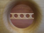
My thing with the chase is whether I want to drill thru the spars and compromise their strength.

Moderator: eaglesdare
![]() by KCStudly » Tue Sep 09, 2014 11:19 am
by KCStudly » Tue Sep 09, 2014 11:19 am
![]() by tony.latham » Tue Sep 09, 2014 1:37 pm
by tony.latham » Tue Sep 09, 2014 1:37 pm
KCStudly wrote:Thanks Tony. I had seen your towel holder before, and it is quite nice!
I was thinking more along the lines of a decorative bobble as a weight on a beaded chain (...550 cord or some such) draped over.
My thing with the chase is whether I want to drill thru the spars and compromise their strength.
![]() by KCStudly » Tue Sep 09, 2014 1:49 pm
by KCStudly » Tue Sep 09, 2014 1:49 pm

![]() by KCStudly » Wed Sep 10, 2014 10:51 pm
by KCStudly » Wed Sep 10, 2014 10:51 pm
![]() by KCStudly » Thu Sep 11, 2014 9:31 pm
by KCStudly » Thu Sep 11, 2014 9:31 pm
![]() by KCStudly » Fri Sep 12, 2014 10:31 pm
by KCStudly » Fri Sep 12, 2014 10:31 pm
![]() by Mary C » Sat Sep 13, 2014 6:02 pm
by Mary C » Sat Sep 13, 2014 6:02 pm


![]() by KCStudly » Sat Sep 13, 2014 8:06 pm
by KCStudly » Sat Sep 13, 2014 8:06 pm

![]() by GPW » Sun Sep 14, 2014 8:43 am
by GPW » Sun Sep 14, 2014 8:43 am

![]() by KCStudly » Sun Sep 14, 2014 8:51 am
by KCStudly » Sun Sep 14, 2014 8:51 am
![]() by GPW » Sun Sep 14, 2014 9:17 am
by GPW » Sun Sep 14, 2014 9:17 am

 Just tell him with these trailers , “you’re never done” ... and see what he says ...
![]() by working on it » Sun Sep 14, 2014 12:21 pm
by working on it » Sun Sep 14, 2014 12:21 pm
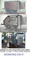
Is he suggesting that you "should be almost done", as a hidden request to finish it soon? How about telling him that you want to start a second build (before the PCE is finished). That'll go over big, I'm sure. Ha Ha. Seriously, My build was started at my friend's shop, at his suggestion, and continued there for 13 months. 50 miles from home, really restricting the time I could work on it. And, for every hour spent working on the trailer, I spent many more hours on other work and cleanup of the shop. And the trailer was moved from one spot to the other, constantly, as it had to be moved for "paying" projects. Eventually, I felt that the time to bring it home for completion (it was still just a shell, after 13 months) was long past due. It strained our friendship to the breaking point, and I wish now that I had never started it there. Hopefully, your build will not be viewed as a divisive point (of even a small magnitude) for you with Karl.KCStudly wrote:Karl keeps saying, "you're almost done", and I suppose relatively speaking I am, but to me there sure do seem to be plenty of things left to do.

![]() by KCStudly » Sun Sep 14, 2014 5:54 pm
by KCStudly » Sun Sep 14, 2014 5:54 pm
... and Karl sort of went along with the idea because it was easier than trying to explain to her how inappropriate all that work would be. I mean, really, you push everything to the middle of the room and tarp it. Why in the heck would you go to the trouble of emptying the house, then haul it up into the loft, only to move it back again. In fact we discussed how he would be off the hook when April came and the camper still wasn't done. ![]() by KCStudly » Sun Sep 14, 2014 9:28 pm
by KCStudly » Sun Sep 14, 2014 9:28 pm
![]() by wagondude » Sun Sep 14, 2014 9:42 pm
by wagondude » Sun Sep 14, 2014 9:42 pm
Users browsing this forum: No registered users and 14 guests
