Am I delusional? 3d interactive wood frame for my foamie.

Canvas covered foamies (Thrifty Alternatives...)

Moderator: eaglesdare

Am I delusional? 3d interactive wood frame for my foamie.

Postby Beagle Appreciator » Thu Feb 22, 2024 8:02 pm

https://app.sketchup.com/share/tc/north ... source=web
The dotted line is where my truck bed ends. (Ignore the line in the very center is is an artifact of my mirrored creation process) I am planning of using between 2 and 3 inches of foam in the walls and roof and 1.5-2 inches in the floor. The solid lines are tension cable supports. The foam walls will have slots for the wood frame cut of out them and then they will be pushed together so the wood frame is inside the foam walls and having been glued everywhere they meet and then taped on the last side. The outside edges and corners will have canvas or similar sheets glued across them. It will be tied down and be supported slightly by the top of the truck (1997 Chevy K1500 Z71) bed walls. Then (and empty highway testing corners movement with high speed camera for structural analysis) I will be mounting 55 lbs of solar panels on the roof with one side articulating perhaps.
I am willing to fail just to learn but would prefer to get it right the first time. Looking for advice from experienced builders or otherwise qualified folks.
Beagle Appreciator
Teardrop Inspector
 
Posts: 3
Joined: Fri Feb 16, 2024 5:59 pm

Re: Am I delusional? 3d interactive wood frame for my foamie

Postby Pmullen503 » Thu Feb 22, 2024 8:43 pm

That's a pretty complex framing job. There are details at the roof/wall intersection at the angled sides that are too complicated to easily implement.

I suggest you start with flat panels, refine the shape so you have no compound curves and then draw in framing. Btw, you have way too much framing. 2" foam covered with canvas or thin plywood siding is self supporting with the spans you are looking at for a truck camper. There are foam truck campers with no structural framing, only enough wood for "hard points" for attachments or doors and windows.

Go to the Dollar Tree, get some $1 foam board and start making some models. Computers let you draw things that are hard to make in practice. There are things you can do with foam board that are hard to draw.
Pmullen503
1000 Club
1000 Club
 
Posts: 1113
Images: 67
Joined: Sun Nov 23, 2014 1:33 pm
Location: Fond du Lac, WI

Re: Am I delusional? 3d interactive wood frame for my foamie

Postby Beagle Appreciator » Thu Feb 22, 2024 9:27 pm

Pmullen503 wrote:That's a pretty complex framing job. There are details at the roof/wall intersection at the angled sides that are too complicated to easily implement.

I suggest you start with flat panels, refine the shape so you have no compound curves and then draw in framing. Btw, you have way too much framing.


I would not at all trust foam only to hold up a cab over sleeping area. Where do you think I could reduce the framing? To be clear the walls extend to about 1 inch inch inside my open mirrors and about 2.5 feet past the end off my truck bed (which will have the tail gate removed since it weighs like 100+ pounds) "Compound curve" is strange as there are no non flat areas as the third derivative everywhere is 0 or inf.
Do you have any input on the back floating area perhaps you didn't notice that?

Thank you for your input already!
Beagle Appreciator
Teardrop Inspector
 
Posts: 3
Joined: Fri Feb 16, 2024 5:59 pm
Top

Re: Am I delusional? 3d interactive wood frame for my foamie

Postby tony.latham » Thu Feb 22, 2024 11:26 pm

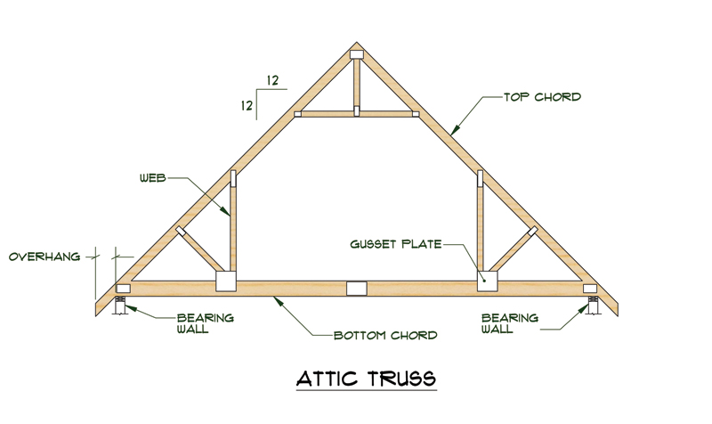
I don't think your roof rafters/trusses will work. Something needs to tie them together or they will push the walls outwards.

Image

Don't be afraid of a flat roof. It will never actually be flat on the back of a truck.

Tony
User avatar
tony.latham
Gold Donating Member
 
Posts: 6900
Images: 17
Joined: Mon Jul 08, 2013 4:03 pm
Location: Middle of Idaho on the edge of nowhere
Top

Re: Am I delusional? 3d interactive wood frame for my foamie

Postby Beagle Appreciator » Fri Feb 23, 2024 12:04 am

tony.latham wrote:I don't think your roof rafters/trusses will work. Something needs to tie them together or they will push the walls outwards.


My assumption is that at this scale outward horizontal forces should not be that large also considering its only 9 and a half feet between the front and back wall. Do you have any calculations or tables that show how much force would be imparted on the walls outwardly? I might add a tension cable between the edge of the second/higher step area to the top of the wall if during the build or otherwise concerns in that direction materialize. 5 degrees of slope is not necessarily enough to shed water and even higher angles is the roof is dusty or dirty and I just do not wanna deal with flat roofs.
Beagle Appreciator
Teardrop Inspector
 
Posts: 3
Joined: Fri Feb 16, 2024 5:59 pm
Top

Re: Am I delusional? 3d interactive wood frame for my foamie

Postby Pmullen503 » Fri Feb 23, 2024 8:12 am

Beagle Appreciator wrote:
I would not at all trust foam only to hold up a cab over sleeping area. Where do you think I could reduce the framing? To be clear the walls extend to about 1 inch inch inside my open mirrors and about 2.5 feet past the end off my truck bed (which will have the tail gate removed since it weighs like 100+ pounds) "Compound curve" is strange as there are no non flat areas as the third derivative everywhere is 0 or inf.
Do you have any input on the back floating area perhaps you didn't notice that?

Thank you for your input already!


I didn't realize you wanted to sleep over the cab. In that case, you'll need to rely on the skin to carry the load. You have no beam running into the sidewalls, the cantilevered sleeping area relies entirely on endgrain fasteners so the framing is going to loosen up over time.. What I would do sheet with thin ply and fiberglass.

The rear overhang has the floor joists to carry the load. I would go with 3/4 wide floor joists on 1 ft centers rather than 2x joints on 2 ft centers. You'll get a stiffer floor with thinner plywood. I'd sheet the underside to make a torsion box.
Pmullen503
1000 Club
1000 Club
 
Posts: 1113
Images: 67
Joined: Sun Nov 23, 2014 1:33 pm
Location: Fond du Lac, WI
Top

Re: Am I delusional? 3d interactive wood frame for my foamie

Postby kd8cgo » Fri Feb 23, 2024 9:51 am

Beagle Appreciator wrote:My assumption is that at this scale outward horizontal forces should not be that large also considering its only 9 and a half feet between the front and back wall. Do you have any calculations or tables that show how much force would be imparted on the walls outwardly? I might add a tension cable between the edge of the second/higher step area to the top of the wall if during the build or otherwise concerns in that direction materialize. 5 degrees of slope is not necessarily enough to shed water and even higher angles is the roof is dusty or dirty and I just do not wanna deal with flat roofs.


https://www.mathscinotes.com/2010/11/th ... llar-ties/

You can calculate the net tension at the rafter tie line (top of walls) using basic statics. Your model does not, at this time, offer any structural member to take up tension loads in the horizontal projection at the midspan rafters. The doorway rafter is well trussed and the opening into the over cab area is supported by columns in the wall structure, once sheathed would provide tension resistance at those two locations. You can approach supporting the midspans in a variety of ways. You can add relatively small plywood or metal gussets at the roof peak that will act as tension members as a collar tie would. You can use upper cabinetry at the wall to rafter interface to act as a combination of purlins and chords in tension along the diagonal between the wall and the inboard rafter tie point of the cabinetry above the doors/openings at each rafter. All loads can be calculated, but you must offer tension resistance in the horizontal projection of the peaked roof or it will bow outward with any, and all, loadings.

For the bed over cab area, the information you are looking for is how to create the appropriate free body diagram to calculate the static forces for a cantilever, or overhang. This is not simple, but it is straight forward, albeit time consuming. You calculate the load of tributory area of the floor, in your drawing example the joists/beams send the floor load to the front edge and the interface. As your solid wood members by themselves are not large enough to contribute meaningful load resistance to the moments that will likely be exerted here, you'll need to distribute the loads through other means of making a trussed beam, sandwich core construction of horizontal decking uses stressed skins to take the loads as an I-beam would and is applicable here, much like in boats that use clear spans with thin section deck spans, they normally use a structural foam and FRP sandwich with the strength required to prevent excess deflection and resulting dynamic loads. Your steel cables at the edges produce a reaction in the angled wall section behind the cab, but those walls are out pf plane with the cable vector, and so there is also a twisting force at the end tie point, very tricky. The cables in the roof terminate at a rafter midspan without anything to support the reaction other than what little the beam profile can withstand, which is not much - this load would rely nearly entirely on skin to support as drawn.

Glen-L uses the side walls of the cabover with plywood to act as the two main stressed members supporting the entire cabover structurally, with the floor section sending the loads side-to-side, rather than front-to-rear as yours does. Some images here: https://www.glen-l.com/cabover-camper-framing/ Your build has no strictly vertical wall segments that project back over the truck bed portion, that would normally act as a tall, engineered beam to take the bending moments produced. Yours will be a very, very difficult design to distribute loads by comparison as it is currently drawn.

Learn enough about free body diagrams and how to make them so you can at least understand the load paths in your build, this will help you locate the force concentrations - then you can calculate the static loads, bending moments, reaction force at each interface, or in each plane.
kd8cgo
Teardrop Advisor
 
Posts: 59
Images: 21
Joined: Sat Aug 04, 2007 12:13 am
Location: MI, USA
Top

Re: Am I delusional? 3d interactive wood frame for my foamie

Postby GTS225 » Fri Feb 23, 2024 10:23 am

Pmullen503 wrote:I didn't realize you wanted to sleep over the cab. In that case, you'll need to rely on the skin to carry the load. You have no beam running into the sidewalls, the cantilevered sleeping area relies entirely on endgrain fasteners so the framing is going to loosen up over time.. What I would do sheet with thin ply and fiberglass.


I'm just an "eyeball engineer", but I have to agree with Pmullen on this. That end grain fastening just isn't going to hold up to the weight of the over-cab sleeper. If it were me, I'd run a 2x4 in the outer walls, from the forward nose of the sleeper, all the way to the rear wall. You'll get a lot more rigidity out of the connection(s).
Well, SHOOT! Just looked at your plan again. Sorta makes it impossible to run a 2x4 as I described, with the main cabin walls flaring out just aft of the truck cab. Not sure what to suggest at this point, but that sleeper is surely going to start separating from the roof over time.

Roger
GTS225
The 300 Club
 
Posts: 300
Joined: Wed Aug 29, 2018 2:11 am
Location: Waterloo, Iowa
Top

Re: Am I delusional? 3d interactive wood frame for my foamie

Postby kd8cgo » Fri Feb 23, 2024 10:34 am

The best thought I've had so far to make the side walls bear the load back over the truck bed portion, would be to extend the cab-over side walls back into the inside of the truck camper, all the way to the rear wall - using a solid construction that would then become cabinet faces for some upper cabinets in the truck bed part of the build. This would be in-plane with the cab over side walls, and also serve as a purlin for the roof rafters in the truck bed segment, solving many of the structural issues with an internal assembly. Sheathed with decently solid plywood, this would make a substantial beam support for the cabover. Then, change the orientation of the floor joists in the cabover to side-to side instead of front-to-rear, or use a structural sandwich panel to distribute that load out to the side walls. Most of the problems then are addressed with a relatively simple addition.
kd8cgo
Teardrop Advisor
 
Posts: 59
Images: 21
Joined: Sat Aug 04, 2007 12:13 am
Location: MI, USA
Top

Re: Am I delusional? 3d interactive wood frame for my foamie

Postby tony.latham » Fri Feb 23, 2024 10:38 am

Do you have any calculations or tables that show how much force would be imparted on the walls outwardly? ...... 5 degrees of slope is not necessarily enough to shed water and even higher angles is the roof is dusty or dirty and I just do not wanna deal with flat roofs.


I don't, it's just common sense. The roof will be pushing outwards on the walls, and thus there will be deflection.

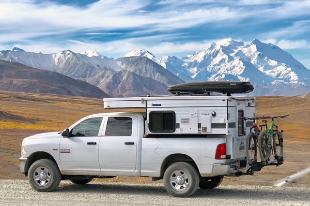
I have several friends that have slide-in truck campers made by Four Wheel Campers. All have flat roofs and none have ever had issues––in fact, if you look at every brand of pickup bed camper, they all have flat roofs. It's an industry standard.

Image

But I think you have your mind made up. :thinking:

Tony
User avatar
tony.latham
Gold Donating Member
 
Posts: 6900
Images: 17
Joined: Mon Jul 08, 2013 4:03 pm
Location: Middle of Idaho on the edge of nowhere
Top

Re: Am I delusional? 3d interactive wood frame for my foamie

Postby ghcoe » Sun Feb 25, 2024 12:40 pm

This would be more of a traditional build using foam for insulation, not a true foamie. Might take it over to the Sketch up designs, Member Designs, Non-traditional Designs or Traditional Designs. They may have better input since they work more with internal wall structural support methods that are not usually used in a true foamie design.

With that being said, I do believe a cab over type camper could be made in a true foamie construction with a little bit of reinforcement.

This is what I had planned in a build that I was going to make. Embed wood the full length of the side wall reaching out into the cab overhang. I would also embed a vertical support for this horizontal support near the front lower bulkhead. This would relieve load strains that would centralize in that area and could possibly cause foam compression. Not sure if it would or not, but better safe than sorry. Then you can attach trusses to the horizonal support to support the sleeping area. I would slide the foam from under the trusses just to keep all the wood imbedded. If foam is glued solidly to the trusses, I doubt that you would even have to add any sheet wood to the sleeping area. Should be plenty of support with the foam alone and trusses.

Camper Overhead Support Ideas s.png
Cab overhang ideas
Camper Overhead Support Ideas s.png (5.9 KiB) Viewed 290 times


I agree, the peek roof will probably cause you issues. If you want some extra head room, I would ether build up to that height or consider a curved roof similar to what Alaskan campers have https://www.bing.com/images/search?q=al ... C3&first=1 .

Good luck! George.
George.

Gorrilla Glue, Great Stuff and Gripper. The three G's of foamie construction.

My build viewtopic.php?t=54099
Working with flashing for foamie construction viewtopic.php?f=55&t=60303
Making a hot wire http://tnttt.com/viewtopic.php?f=55&t=55323
User avatar
ghcoe
1000 Club
1000 Club
 
Posts: 1946
Joined: Fri Dec 11, 2009 11:20 pm
Location: SW Idaho
Top

Re: Am I delusional? 3d interactive wood frame for my foamie

Postby Squigie » Wed Feb 28, 2024 10:55 am

That's a pretty tight sleeping area in the cabover bunk. And with a small entry.
You may want to mock that up and see what it is actually like to climb into a confined space like that, through a hole that small.
User avatar
Squigie
The 300 Club
 
Posts: 403
Joined: Sun Aug 04, 2019 7:52 am
Location: Southeastern ID
Top


Return to Foamies

Who is online

Users browsing this forum: No registered users and 24 guests